Digital Power & Associates Ltd.
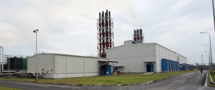
Project Details : Digital Power & Associates Ltd.
About us
Owner of this Company : Mohammad Obaidul Karim
MD of this Company: Salman Obaidul Karim
Date of Installation : June 9, 2014
Number of employees: 132 (Including operation and maintenance)
Major Equipment & installment:
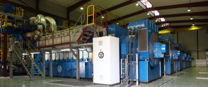
- Engine : 12 Nos. Model: W20V32 from Wartsila Finland
- Alternator : 12 Nos. Model DIG 167 f/8 from AVK Germany
- Starting Compressor : 02 Nos, Model Atlascopco, Belzium
- Ins Air Compressor : 02 Nos. Model Atlascopco, Belzium
- EGB : 04 Nos. Alborg
- Aux Boiler : 01 No. Alborg
- BSU : 01 nos. 375 KVA
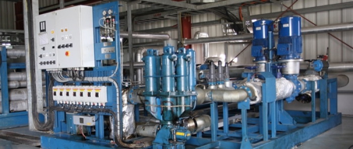
- Fuel Purifier : 03 Nos. Model OSE 80, Westfalia, Germany
- LO Separator : 12 Nos. Model OSE 20, Westflia, Germany
- Firefighting equipment: 1 Nos.
- ETP : 01 Nos
- Storage Tank : 02 Nos. Capacity 4000 CM each
- Day Tank : 01 Nos. Capacity 200 CM
- Buffer Tank : 02 Nos. Capacity 100 CM each
Fuel
We have our own jetty where we can received HFO through fuel tanker. According to draft we can receive fuel from 10 Lac ltr to 20 lac ltr/Tanker. We have a storage capacity of 80 lac ltr.
Our daily consumption of fuel is around 5 lac ltr at full load. We have 3 types of fuel tank 1. Main storage tank, 2 set ( 4000 CM each) 2. HFO buffer Tank 1 ( 100 CM) and 3. HFO day Tank 1 ( 200 CM). From main storage tank fuel is transferred to buffer tank for preliminary settlement and from buffer tank it is transferred to day tank after purification. We have 3 set of purifier from Westfalia, Germany of capacity 15 cm/hr.
From day tank it goes to the engine through the feeder unit and filter.
Basic Principle power production:
The internal combustion engine is the power source for alternator. Its basic operating principle is that combustion, or the controlled, steady burning of air and fuel in the combustion chamber, creates power that forces components within the engine to move with great speed and force. The motion and force is transferred to the Alternator through components of other systems.
An understanding of the internal combustion engine, or ICE, requires an overview of the engine's major components. The components in direct contact with combustion are the cylinders, pistons, valves, fuel pump and Injector. Air from the vehicle's intake system and fuel from the fuel system is delivered to an area at the top of each cylinder known as the combustion chamber. Intake and exhaust valves are seated in holes at the top of the combustion chamber. When the intake valve opens, a measured amount of air entered through Turbocharger and CAC and after compression fuel injected into the chamber and combustion takes place. Within each cylinder, a piston moves up and down. Pistons are strong, cylindrical metal components whose tops form the base of each combustion chamber. Once air are delivered to the combustion chamber and the piston is traveling upward, the mixture is compressed. The Injector then inject fuel and the compressed mixture ignites.
The ignition of compressed air and fuel exerts a tremendous amount of force on the top of the piston, moving it downward in the cylinder. At this point, a few other components must be mentioned: the connecting rod and crankshaft. A connecting rod is attached to the inside of each piston. The bottom end of the rod connects to a section of the crankshaft. Crankshafts have numerous sections that are not in-line; some sections fall in the center-line, and others are offset. The offset sections are surrounded by the bottom ends of the connecting rods. When the piston is forced downward, the connecting rod moves with it. The rod forms a link between the piston and the crankshaft, yet the design of the crankshaft causes its motion to be rotary rather than up-and-down. The crankshaft rotates when the connecting rod applies force to it. A component called a flywheel (in vehicles with manual transmission) or a torque converter (in vehicles with automatic transmissions) is connected to one end of the crankshaft.
Once the piston has moved downward after combustion, the rotary motion of the crankshaft moves it back up the cylinder. At this time, the exhaust valve is opened and the leftover gas from combustion called exhaust is forced out of the chamber.
Once this valve closes and the piston moves downward again, the intake valve opens and the partial vacuum created by the piston's downward motion pulls more mixture into the chamber. Valve timing is controlled by the camshaft, a component that is linked to the crankshaft. The camshaft turns as the crankshaft does, but at half the speed. It is composed of lobes, or egg-shaped knobs whose longer ends push on valves directly or on components linked to valves to open them. Once the lobe's long end comes off the valve or linked component, spring pressure returns the valve to its seated, closed position.
It requires a starter motor to begin the motion. The motor turns the crankshaft, which transfers its motion to the connecting rod and piston. The piston then compresses the air and fuel mixture in the combustion chamber. Once combustion has occurred, the force created thereby moves the crankshaft through the connecting rod. The crankshaft's inertial motion works to keep the piston moving up and down the cylinder, and the process of combustion continues for as long as the system is required.
Alternator Principle:
A.C. generators or alternators (as they are usually called) operate on the same fundamental principles of electromagnetic induction as D.C. generators.
Alternating voltage may be generated by rotating a coil in the magnetic field or by rotating a magnetic field within a stationary coil. The value of the voltage generated depends on-
- the number of turns in the coil.
- strength of the field.
- the speed at which the coil or magnetic field rotates.
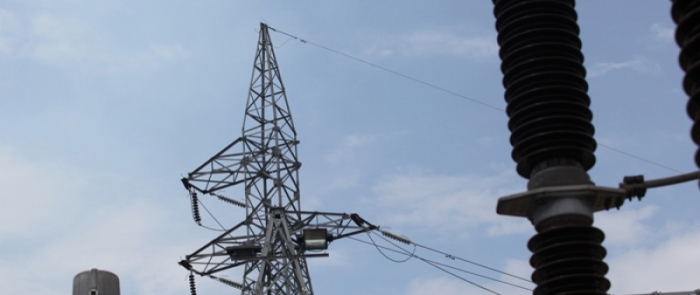
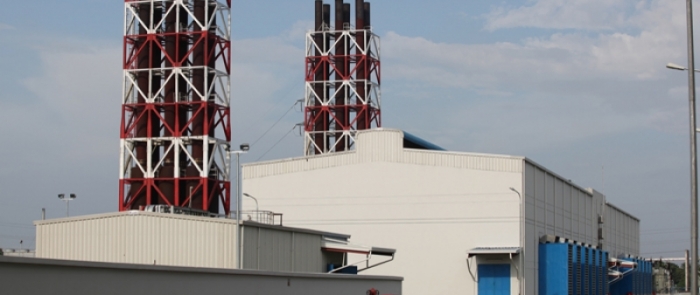
Switch Yard:
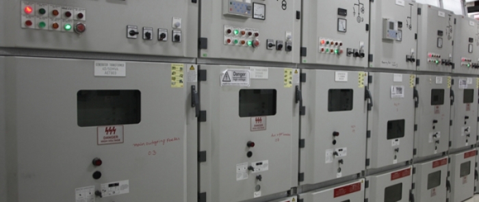
We have a switch yard of capacity 150 MVA, 11kv to 132 KV. There are 3 transformer having capacity 40/50 MVA from ABB, Switzerland . Our 11 KV line is connected with each transformer incoming terminal through switch gear, it is then step up to 132 KV which is connected to the national grid through isolator and breaker. It is under Shitalakha Substation, DPDC.
ETP:
We have a built-in ETP system, All rejected oily water accumulated in the oily water sludge tank then through oily water separator pure water drain in the rain pit and sludge accumulated in the sludge tank. This sludge is then taken away by the vendor who have the license from environment.
Fire fighting System:
We have our own fire fighting system by which we can fight 6 hours continuously. The whole are is covered with fire alarm and smoke detector. We have 2 types of fire fighting system,
- Extinguisher Type
- Fire hydrant
Extinguisher: We have different type of extinguisher such as CO2, Foam. 45 sets of CO2 is located in different places and 3 Foam extinguisher also.
Fire hydrant: we have self fire hydrant system of capacity 700 CM. We have 3 types of pumps for firefighting like diesel driven pump, electrical driven pump and jockey pump. We have a huge no of hydrant in different location which covers the whole area.
Safety and Security:
For safety and security of the plant we have 3 types' security forces
- Arm force battalion, Ansar - 22 Persons
- Orion Security - 10 Persons
- Hired security force-Elite Force - 16 Persons
They always keep watching the whole plant to maintain the safety and security of the plant.
Plant Facility:
For safety and security of the plant we have 3 types' security forces
- Workshop with well equipped to handle the power plant maintenance.
- Laboratory with well equipped to meet the power plant requirements.
- Well decorated Warehouse.
- Comfortable accommodation.
- First Aid
- PPE
- Canteen facilities
- Welfare
- Transport facilities
- Fire fighting's
They always keep watching the whole plant to maintain the safety and security of the plant.
We have a cleaning agency:
- SATCO : 21 persons
For the employee we have following PPE.
- Safety shoe
- Helmet
- Ear muff
- Safety glass
- Working dress
- Hand gloves
We have well equipped fire fighting system.
Employee's Welfare
- We have welfare fund for the employee.
- We have medical facility.
- We have Insurance.
- We are supporting the employ who are affected by flood.
We have well equipped fire fighting system.
Employee's Medical Services
- We have medical facility.
- Emergency treatment.
- First Aid Box.
- Insurance.
Conclusion:
Every day we are producing electricity as per the requirement of NLDC, BPDB and from last 3 months we running this project successfully with maintaining all rules and regulation. In previous 3 months we don't have any lost time injury and incident. It is an idle plant in all respect.